What is a COB LED strip light
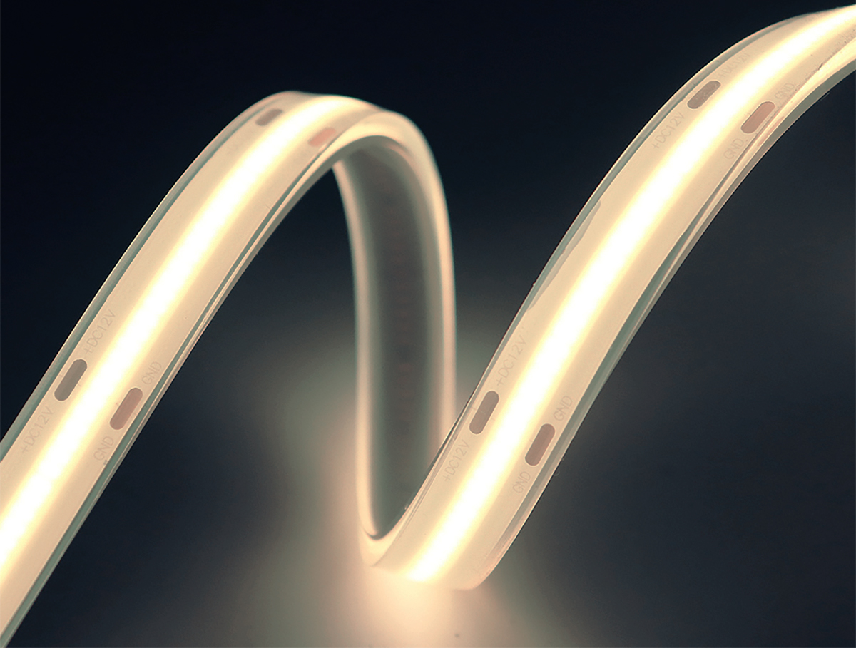
A COB LED strip light is a linear chip-on-board LED array fabricated on a flexible printed circuit board. Chip-on-board (COB) technology enables creation of a homogeneous light emitting surface (LES) that is impossible with SMD technology. The introduction of COB technology to flexible linear lighting applications creates yet another innovation. COB LED strips are capable of delivering a continuous run of lighting without any visible individual light points. The ability to provide truly seamless illumination without shadows makes the COB light strip a fantastic product for use in architectural and decorative lighting applications.
FCOB technology
COB LED strip lights are also known as FOB or FCOB LED strips. Most people would associate the letter “F” in the abbreviations with the word “flexible”. It sounds pretty reasonable from an end-user perspective. However, technically the names were derived from the flip chip-on-board (FCOB) technology, which is the driving force behind the innovation. In a conventional COB package, an array of LED dies (chips) are wire-bonded with aluminum or gold wires and die-bonded on a metal-core printed circuit board (MCPCB) or ceramic substrate with silver-filled epoxy. The die matrix is then covered with a phosphor silicone mixture to enhance light uniformity, provide wavelength conversion, and to shield the chip array from the environment.
Substrate-based COB packaging
The conventional COB packaging technology that uses wire bonding for electrical connection has been around for many years and worked reasonably well despite a number of limitations. Nevertheless it is a mission impossible for flexible LED strips to harvest the benefit of COB LED lighting with the conventional packaging technology. Wire bonding requires special considerations the substrate. Conventional COB LEDs must be fabricated on a level (and rigid) substrate otherwise the bonding wires will break. Flexible LED strips must tolerate continuous and repeated bending because a minimum bending radius and high bending stability are often required when they’re installed into coves, bannisters, recesses, furniture, counters, stairways, and other irregular constructs.
FCOB packaging advantages
FCOB packaging flips over the LED chips in a face down orientation and places the electrodes in direct contact with the circuit board. The bare semiconductor die is directly mounted onto the PCB using bump bond connections. Solder bumps are placed on the die’s bond pads and are then reflowed to provide both mechanical and electrical connection to flexible PCB. Bump bonding intrinsically overcomes the laminations with wire bonding. The removal of wire bonding is the key element in the implementation of COB packaging on a flexible circuit board. The flip chip architecture enables relatively large area contacts that serve as both electrical and thermal pads to be created. This design presents enormous advantages which including improved solder joint reliability, improved heat dissipation efficiency, an increased LES as a result of the elimination of wire bond shadowing.
The flip chip LEDs can be packaged in a very small pitch, allowing COB LED strips to create a very homogeneous, high lumen density light output. The large anode (positive electrode) and cathode (negative electrode) electrodes allow electrical current to be distributed evenly, thereby reducing the risk of thermal runaway due to current crowding. For applications where high current handling capability is required, FCOB LED strips present crucial advantages. However, COB LED strips with a high mounting density of chips or driven as a high current density should not be operated in a hermetically sealed waterproof housing which blocks the thermal path from the LED junction to the ambient environment.
Phosphor application
A very practical concern with COB LED strips is the on-board phosphor coating. To achieve color consistency across the entire run, the phosphor silicone mixture (encapsulant) must be uniformly applied to the LEDs. The probability of delamination between the circuit board and encapsulant must be reduced to a minimum. Thermomechanical stresses, moisture absorption, as well as interface contamination during the phosphor dispensing process can reduce interfacial adhesion strength and lead to delamination.









Loading...