What is an explosion proof high bay or low bay light
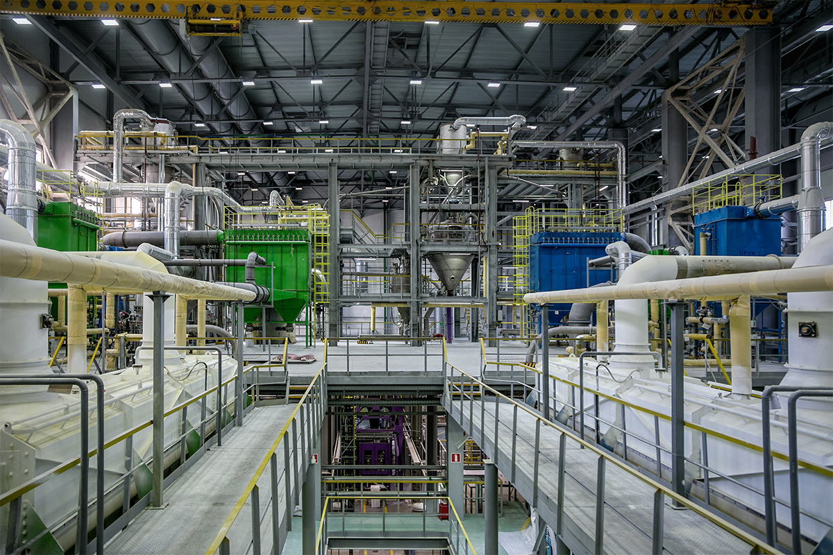
An explosion proof high bay or low bay light is an industrial-grade light fixture designed for use in hazardous locations where atmospheres may be exposed to the release of flammable gases or vapors, combustible dusts or ignitable fibers or flyings in explosive concentrations. Typical hazardous environments form in high bay and low bay facilities such as oil and gas processing facilities, petroleum refineries, chemical plants, solvent extraction plants, powdering and lacquering facilities, saw mills and wood-processing facilities, pulp and paper mills, ammunition and fireworks manufacturing and storage facilities, flour silos, grain processing and storage terminals, coal preparation and processing plants, aircraft hangers and fuel servicing areas, pulverized sugar and cocoa packaging and handling plants, and confectionary manufacturing plants.
Explosion proof lights are built to operate safely in these environments. These luminaires are designed in a way that they will never constitute a source of ignition of the surrounding hazardous gas or vapor while standing up to the demanding conditions faced in industrial environments.
Hazardous (classified) locations
The requirements for hazardous location lighting are complex. Lighting equipment used in a hazardous location environment must be certified to meet the explosion proof standards established by a variety of organizations throughout the world who govern electrical installations or industrial safety. In North America, the hazardous nature of the space and the requirements for lighting equipment suitable for installation in hazardous locations are defined by the NFPA Publication 70 or National Electrical Code (NEC) published by the National Fire Protection Association (NFPA) of the United States (U.S.), and the Canadian Electrical Code (CEC) published by the Canadian Standards Association.
Whether or not luminaires are safe and can be used in the NEC category for which they were designed is determined by Nationally Recognized Testing Laboratories (NRTLs) such as Underwriters Laboratories Inc. (UL) and Intertek (ETL). These agencies independently test the products in accordance with the hazardous location luminaire standard ANSI/UL 844 “Standard for Luminaires for Use in Hazardous Locations” or CSA C22.2 No. 137 “Electric Luminaires for Use in Hazardous Locations”.
In other parts of the world, the IECEx System, or the International Electrotechnical Commission (IEC) System for Certification to Standards Relating to Equipment for Use in Explosive Atmospheres, works to standardize and harmonize international explosion protection standards. The IECEx system is technically identical to the European Union’s ATEX Directive which is a continuance of CENELEC (the European Committee for Electrotechnical Standardization) standards.
ATEX/IECEx
Under IEC/CENELEC standards classifications of hazardous locations where flammable gases and vapors are present are divided into Zone 0, Zone 1, and Zone 2. Zone 0 locations are areas where explosive gas atmosphere consisting of a mixture with air of flammable substances in the form of gas, vapor or mist is continuously present or present for long periods of time. Zone 1 locations are area where explosive gas atmosphere consisting of a mixture with air of flammable substances in the form of gas, vapor or mist is likely to occur in normal operation or can be expected to be present frequently. Zone 2 locations are areas where explosive gas atmosphere consisting of a mixture with air of flammable substances in the form of gas, vapor or mist is not likely to occur under normal conditions and if it does, it will persist for a short period of time.
The combustible dust locations are divided into Zone 20, Zone 21, and Zone 22. Zone 20 locations are areas where an explosive atmosphere in the form of a cloud of combustible dust in air is present continuously or frequently during normal operations in sufficient quantities to produce an explosive mixture. Zone 21 locations are areas where an explosive atmosphere in the form of a cloud of combustible dust in air is likely to occur during normal operations in sufficient quantities to produce an explosive mixture. Zone 22 locations are areas where an explosive atmosphere in the form of a cloud of combustible dust in air is not likely to occur, but may occur infrequently and persist for only short periods of time.
The IECEx/ATEX classification system places each gas into one of three groups depending on its ignition point, which are Group IIC (acetylene, hydrogen), Group IIB (ethylene), and Group IIA (propane). The combustible dusts are divided into 3 groups depending on their electrical resistance, which are Group IIIC (conductive dust), Group IIIB (non-conductive dust), and Group IIIA (combustible flyings).
NEC/CEC
The NEC and CEC divide hazardous locations into three broad classes (Class I, Class II, or Class III) based on the explosive characteristics of the materials. Each of the three classes is further subdivided into two divisions based on the risk of fire or explosion that the material poses. The nature of the flammable or explosive substances that fall into Class I and Class II divisions is classified by group. Class I locations are areas where flammable gases, flammable liquid-produced vapors, and combustible liquid-produced vapors are present. Class II locations are those made hazardous by a combustible dust. Class III locations are areas made hazardous due to the presence of easily ignitable fibers or flyings.
Under each class there are Division 1 and Division 2. Division 1 applies to an area where the hazardous condition would normally exist, while Division 2 applies to an area where the hazard is not likely to occur under normal conditions. The gases and vapors of Class I are divided into four groups: Group A (acetylene), Group B (hydrogen), Group C (ethylene), and Group D (propane). Within Class II there are another set of groups, which are Group E (electrically conductive dust), Group F (carbonaceous dust), and Group G (agricultural and polymer dust).
NEC has recently introduced the Zone system for flammable gas and combustible dust locations in an effort to closely align to the ATEX/IECEx principles. Zone 0 locations are areas where ignitable concentrations of flammable gases, flammable liquid-produced vapors, or combustible liquid-produced vapors are present continuously or for long periods of time under normal operating conditions. Zone 1 locations are areas where ignitable concentrations of flammable gases, flammable liquid-produced vapors, or combustible liquid-produced vapors are likely to occur under normal operating conditions. Zone 2 locations are areas where ignitable concentrations of flammable gases, flammable liquid-produced vapors, or combustible liquid-produced vapors are not likely to occur under normal operating conditions and do so only for a short period of time.
Zone 20 locations are areas where ignitable concentrations of combustible dust or ignitable fibers/flyings are present continuously or for long periods of time under normal operating conditions. Zone 21 locations are areas where ignitable concentrations of combustible dust or ignitable fibers/flyings are likely to exist occasionally under normal operating conditions. Zone 22 locations are areas where ignitable concentrations of combustible dust or ignitable fibers/flyings re not likely to occur under normal operating conditions. The flammable gases (Class I, Zone 0, 1 and 2) are divided into Group IIC (acetylene, hydrogen), Group IIB (ethylene), and Group IIA (propane). The combustible dusts (Zone 20, 21 and 22) are categorized into Group IIIC (conductive dust), Group IIIB (non-conductive dust), and Group IIIA (combustible flyings).
Explosion proof protection
The protection concept of an explosion proof light works by enclosing the light engine and electrical system inside a robust housing which enables exclusion of the ignition source from the ambient environment. An explosion protected luminaire designed for use in NEC Class I, Division 1 or equivalent ATEX/IECEx Zone locations is enclosed in a manner that every path from the inside of the luminaire enclosure to the outside (designed for the passage and escape of a burning gas), called a flame path, is controlled. The enclosure must be strong enough to contain an explosion and prevent the ignition of a specified gas or vapor surrounding the enclosure by arresting any sparks, flame, hot gases or flashes created inside the fixture.
The flame path is designed to provide an escape route for the exploding gases and allows the hot gases generated during an internal explosion to be cooled below the ignition temperature of the surrounding flammable atmosphere as they exit the enclosure. Class I, Division 2, Class II, III, or ATEX/IECEx Zone 21/22 locations are usually illuminated by dust-ignition proof luminaires which are enclosed to keep combustible dusts or ignitable fibers / flyings from entering luminaire enclosures. Explosion proof lights must operate below the ignition temperature of the hazardous substance to avoid thermal ignition of the surrounding flammable atmosphere or the dust layer on the enclosure.
LED technology
LED technology has rapidly taken center stage in hazardous location lighting applications. Long lifespan, high efficiency operation and solid state durability drive a significantly high return on investment (ROI). Conventional lighting technologies suffer from a number of disadvantages. The use of fluorescent and HID lighting is extremely common for explosion proof applications, but it leaves facility managers with challenges including excessive energy consumption, low lighting application efficiency (LAE), and expensive lighting maintenance.
LEDs are semiconductor devices which employ the principle of injection electroluminescence. This nature not only gives LED lights the ability to deliver huge energy savings resulting from improvements to light source efficiency as well as optimized holistic lighting performance, but also lends enhanced safety to explosion proof lighting. The spark free ignition of LEDs means that the explosion hazard is not characteristic of LED lighting; this is in contrast to HID sources which operate at high pressures and very high temperature.
As connected lighting that runs on Internet of Things (IoT) platforms has taken off, it’s important to futureproof industrial lighting systems to be able to work with lighting controls. While LED lighting addresses the growing demand for controllability with instant dimming and turn on-off capabilities, HID and fluorescent lamps are lower performers in dimming control and prone to premature failures when they undergo constant switching cycles.
Flame path construction
An explosion proof high bay or low bay LED light has a rugged construction for failure-free operation in demanding environments. The enclosure is die cast from low copper aluminum that adds to the strength and corrosion resistance of the luminaire while facilitating transfer of the LED heat flux to the environment. Mechanical strength and flame path design are critical to the explosion protection performance of Class I or ATEX/IECEx “Ex d” LED luminaires. The optical compartment and electrical enclosure must withstand the pressure developed during an internal explosion of an explosive mixture, while the engineered flame path must have an adequate length and a narrow interstice to guarantee the cooling of the burning gases. To ensure that the luminaire meets the safety requirement, a hydrostatic pressure test of four times the maximum pressure from an explosion within the enclosure is carried out.
Luminaires certified for Class II and Class III or ATEX/ IECEx Zone 2, 21 and 22 hazardous locations are dusttight equipment sealed to exclude dust from entering the enclosure and to prevent hot particles, arcs, sparks or heat generated or liberated inside of the enclosure from igniting an exterior accumulation or atmospheric suspension of combustible dusts on or in the vicinity of the enclosure. “Ex d” LED luminaires are often designed as dusttight systems and have watertight integrity. The high degree of ingress protection (e.g. IP66 or IP67) allows these luminaires to be used in hazardous locations other than Class I areas or ATEX/IECEx Gas zones. To prevent moisture and corrosive atmospheres from deteriorating metal structures, surface treatments of the aluminum enclosure are applied for the purpose of creating a barrier between the corrosive environment and the aluminum surface and improving the adhesion of subsequently applied organic powder coatings.
Thermal engineering
Explosion proof lighting based on LED technology calls for the most thoughtful thermal design. For general lighting applications, the aim of thermal management for LED systems is to transfer the heat generated by the LEDs into the ambient air to prevent components overheating. Thermal design revolves around keeping the junction temperature as low as possible. The cooler the p-n junction of an LED remains during operation, the better lumen maintenance and color stability the LED will have.
In hazardous location lighting applications LED luminaires must run cooler than the ignition temperature of the surrounding atmosphere. Ignition temperature or auto-ignition temperature (ATI) is the minimum temperature required to cause ignition of an explosive atmosphere at normal atmospheric pressure in the absence of a spark or flame. Flammable gases and vapors and gases are classified into T1 to T6 temperature classes, whereas the maximum surface temperature of dusts is directly reported in °C. Hazardous listed luminaires are defined by their T-code rating which designates the maximum operating temperature of luminaires at 40°C (104°F) ambient temperature.
The T-code rating imposes rigorous requirement on the temperature control of the luminaire’s hottest surface at which ignition of the gas, vapor or dust occurs. To ensure an explosion proof LED light operates at a safe surface temperature, tight drive current control and optimization of the thermal path are critically important. The LEDs should be driven by an appropriate forward current to avoid excessive heat generation within the LED packages. Thermal capacity of an LED lighting system is a function of thermal conduction and thermal convection. In addition to a robust thermal conduction path, the heat sink of an explosion proof light should be provided with an adequate surface area to facilitate thermal convection and to spread the heat out over the large area for minimizing heatsink surface temperature.
System integration
Explosion proof LED lights come in various form factors, lumen packages, color characteristics and light distributions. The performance and lifespan of LEDs depend on the package platform they are built on as well as the thermal, optical, and electrical systems applied. The use of high power LEDs is extremely common for hazardous location lighting applications because of the reliability offered by these ceramic based packages. The LEDs are mounted on a metal core printed circuit board (MCPCB) with strong interconnects created to withstand thermal cycling and vibrations. The directional output and small package sizes allow for the use of secondary optics that enable precisely controllable light distributions.
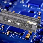
The LED array is operated by a constant current LED driver which is often enclosed in a dedicated housing or compartment for thermal isolation with the light engine. The LED driver is typically designed to operate across a universal input voltage (e.g., AC 120-277 or 347-480V) to provide a near unity power factor and a low total harmonic distortion (THD). The DC-DC converter which is often a switching power supply (SMPS) then provides tight regulation and control on the current fed to the LED array. System reliability is maximized with overcurrent/overvoltage/short-circuit protection and intelligent temperature monitoring of the LED light engine.






Loading...