Table of Contents Hide
- 1 Infrastructure Lighting
- 2 What Is an LED Street Light
- 3 How Do LEDs Work
- 4 Advantages of LED Street Lighting
- 5 Construction
- 6 Light Source
- 7 Thermal Management
- 8 LED Driver
- 9 Surge Protection
- 10 Dimming Control
- 11 Lighting Control
- 12 Light Controllers
- 13 Secondary Optics
- 14 Light Distribution
- 15 Luminaire Classification System (LCS)
- 16 Ingress Protection
- 17 Protection against Corrosion
Infrastructure Lighting
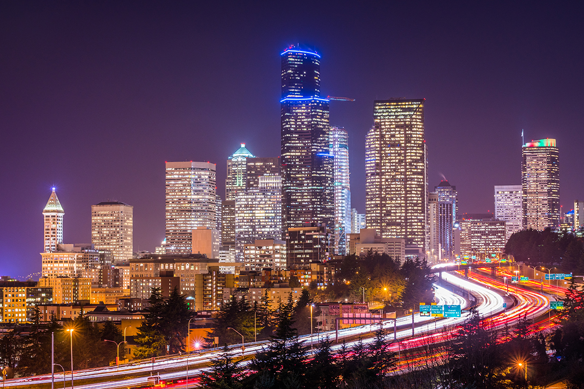
Street lighting is an integral part of road infrastructure and makes a decisive contribution to nighttime traffic safety. An enhanced visual environment enables drivers to detect roadway hazards and traffic conflicts across a distance that allows appropriate action in sufficient time. There is a consensus of statistics indicating that good roadway visibility during the night significantly reduces vehicle collisions and pedestrian fatalities.As the primary component of public lighting, street and road lighting offers a plethora of benefits not directly related to driving. Lighting of roadways and other outdoor traffic zones can deter criminal activities by increasing fear of detection and create a perception of security which enhances pedestrian confidence. Increased road visibility and enhanced public security may draw people into commercial areas and thus promote evening economy. Lighting also draws attention to streetscapes and reinforces aesthetic appeal of adjacent architectural elements. With the arrival of the Internet of Things (IoT), there is a trend toward transforming street lights into network nodes to receive, collect and transmit information.
Therefore, a roadway system is deployed with a large number of street lights which provide visibility for drivers and pedestrians while communicating information about the surrounding environment to both groups of viewers, and also possibly to a smart city platform.
What Is an LED Street Light
LED street lights are semiconductor-based roadway lighting systems designed to provide energy efficient, dependable, and visually comfortable lighting for people to safely use the roadway system during hours of darkness.When we talk about a street light that harvests a specific type of lighting technology, we're usually referring to the luminaire that is mounted to a street light pole such as a davit-style, truss-style, or mast-arm pole. A street light generally comprises a housing, a light assembly, an optical system, and an electrical power supply. The housing provides support, protection, and heat sinking for internal components. The light assembly can be an LED light module or a conventional light bulb which is most often a high-intensity discharge (HID) lamp, and in some cases can be a fluorescent lamp. The optical system is used to control light distribution. The electrical power supply regulates power supplied to the LEDs or provides the proper starting and operating voltage for the HID lamp. Despite the similar architecture between different technologies, the design and engineering disciplines of LED street lights are fundamentally different from conventional street lights.
Although the retrofit type LED street lights generally use self-driven LED bulbs of the same form factor with the HID light bulbs to be replaced, LED street lights for new construction projects are prevalently integrated lighting systems which come with factory-assembled LED modules. An LED module is an assembly of LED packages on a printed circuit board (PCB), usually with an optical lens indexed to the PCB. Direct integration of LED modules offers a multitude of benefits, which include efficient thermal dissipation, flexible beam control, a large light emitting surface (LES), a uniform light distribution, and a compact system form factor.
How Do LEDs Work
It is important to understand the working principle of LEDs before exploring the depths of LED street lighting. An LED or a light emitting diode has a p-n junction formed between an n-doped semiconductor layer and p-doped semiconductor layer. When a sufficient forward voltage is applied across the p-n junction, electrons from the n-doped semiconductor layer and holes from the p-doped semiconductor layer flow toward the p-n junction and recombine. When recombination of an electron and a hole occurs, the electron drops into a state of lower energy and the excess energy is released in the form of a photon that transports electromagnetic radiation in the visible spectrum. This effect is known as electroluminescence. Contemporary LEDs takes advantage of the large energy band gap in gallium nitride (GaN), which allows photons to be emitted at wavelengths in the blue spectrum range when the active region (p-n junction) is grown with different concentrations of indium-gallium nitride (InGaN).The electroluminescence that occurs in an InGaN LED produces monochromatic blue light. Since white light is a mixture of multiple visible wavelengths, the blue emission from the LED is then be converted to a polychromatic white light through a combination of photoluminescence and color mixing. The LED chip is coated with a phosphor mixture which down-converts a portion of the blue wavelengths into longer wavelengths. The remaining blue wavelengths mix with the longer wavelengths to create a mixture of light that is perceived as white by the human eye. The phosphor coating is an important component of an LED package since it determines the spectrum properties of the white light emitted by the LED, such as correlated color temperature (CCT), color rendering index (CRI), and chromaticity coordinates.
Advantages of LED Street Lighting
Street lights have profited greatly from LED technology which produces light by generating radiative electron-hole recombination in solid state semiconductors, rather than by exciting a gaseous medium or heating a thermal radiator in glass envelopes or enclosures. Solid state lighting technology offers compelling advantages over HID systems including high-pressure sodium (HPS), low-pressure sodium (LPS), metal halide (MH) lamps.The biggest drive that spurred on the shift from HID (HPS, LPS, MH) to LED is the substantial energy savings offered by LED technology. HPS lamps, the ever most popular street light source, can hit a source efficacy as high as 150 lm/W in high wattage products, however in real world applications their source efficacy is around 100 lm/W. When the optical and ballast losses are taken into account, the system efficacy of HPS street lights can drop by 30% - 40%. Whereas phosphor converted LEDs have a potential source efficacy of 255 lm/W, a commercially available source efficacy over 200 lm/W, and financially economical source efficacies between 150 and 190 lm/W. High source efficacy combined with the directional emission pattern of LEDs and high power conversion efficiencies of LED drivers allows LED street lights to achieve a system efficacy of well over 140 lm/W, and a luminaire efficiency approaching 80%. This means LED street lighting brings about 50% - 100% energy savings over conventional technologies.
The maintenance and life cycle cost savings offered by LED street lights also appeal to municipalities and utilities who strive to cut down the operation and relamping cost. LED lighting systems with good thermal management and optimal power regulation can have an operation life of more than 50,000 hours. LEDs are constructed from a block of semiconductor, and do not use glass envelopes or fragile components. The solid state durability of the light source allows LED street lights to survive repeated vibration caused by vehicles traveling at a high rate of speed. Excellent reliability and durability collectively contribute to the long useful life of LED systems and a dramatic reduction in maintenance and relamping.
The spectral power distribution (SPD) of LED street lighting can be optimized for nighttime driving conditions. The visibility provided by a lighting system can be affected substantially by the spectral characteristics of the light source. The human eye contains two visual photoreceptors: rods and cones. Rods are responsible for night vision (scotopic vision) where the luminance level is very low (<0.005 cd/m²). The cones can respond to all colors in the visible spectrum and are most active under photopic conditions where the luminances are generally in excess of 3.4 cd/m². The spectral sensitivity curves for photopic vision and scotopic vision peak at 555 and 507 nm, respectively. The area between photopic vision and scotopic vision is referred to mesopic vision which is responded to by the rod photoreceptors.
By adjusting the ratio of phosphors for the desired colors in down-converters, the light spectrum of LED street lights can be modified to target the most effective spectrum for the roadway vision states, in particular the mesopic vision which applies to the light levels frequently found in street lighting. A good scotopic vision is also important for the eye to detect off-axis objects. Visual acuity has limited importance in visibility for a driver, but a good color rendition allows the cone photoreceptors to be activated and thus makes small objects easier to distinguish from their background. Compared with the poor CRI of HPS lamps, LED street lights typically have a CRI of 80 which is sufficiently good for roadway lighting. In general, a light spectrum with a high scotopic / photopic (S/P) ratio is preferred in order to ensure high visual performance in mesopic vision. HPS lamps has a typical S/P ratio of 0.63, whereas LED street lights can be spectrally tuned to offer an S/P ratio from 1.21 (3000 K LED) to 2.0 (6000 K LED).
A high S/P ratio doesn't always mean good visibility. For conditions with a low meteorological visibility due to the existence of a high density of fog, mist or haze in the atmosphere, higher the S/P ratio is, the more the light is scattered and the less the light is transmitted. High S/P-ratio light contains a high percentage of blue wavelengths in its light spectrum. This raised the concerns on the blue light hazard and physiological impact of high intensity and high CCT street lighting. While the blue-rich cool white light should not be used in indoor lighting during the night to avoid circadian disruption, the light spectrum for roadway lighting may require a minimum content of blue or a moderate S/P ratio to provide good visibility as well as to create alertness and suppress the release of melatonin (which is known as a sleep hormone). As such, LED street lights with a color temperature of 4100 K are typically recommended for high way and freeway lighting. In densely populated regions and residential areas, the negative physiological impact of street lighting should be reduced to a minimum and therefore warm white light (e.g. 3000 K) is suggested. Whatever the CCT requirement, LED technology can do the job.
LEDs are semiconductor devices that can work seamlessly with other solid state circuits. Because LEDs react instantaneously to changes in power input, analog dimming based on the constant current reduction (CCR) technique can be implemented by simply controlling the drive current fed to the LEDs. LED street lights can also be digitally dimmed using a pulse width modulation (PWM) technique, which enables full range intensity control while maintaining a consistent color point regardless of the variation in light intensity. In contrast, HPS street lights can only be dimmed to roughly 50% light level and dimming MH lamps is more difficult. The digital nature of solid state lighting opens up opportunities for direct integration of street lights into computer-based systems, and resulting in improved efficiency and automation. This combination of street lighting, sensor technology, and wireless communication opens the door to a wide range of innovative capabilities in the context of IoT.
Construction
A typical LED street light has a two-piece die cast housing which consists of a canopy and a frame. The canopy has two cavities which hold the LED assembly and electrical components, respectively. Two corresponding cavities of the frame form two enclosed compartments with the canopy when they're hinged together. The bottom cavity of the LED compartment has a clear tempered flat glass lens. The glass lens is sealed to the frame with an extruded one-piece gasket and fixed with metal clips. The LED assembly mounts flat to the heat sinking surface of the canopy. The LED compartment may be additionally sealed with a gasket for enhanced ingress protection. The electrical compartment contains the LED drivers, control gears, surge protection module, and terminal block. They are generally mounted onto a gear tray for ease of maintenance. A safety switch is installed in the electrical compartment to disconnect power on opening. The hinged assembly of canopy and frame is sealed by a master gasket and has quick-release latches for easy, tool-less access to electrical and LED compartments.LED street lights that use modular light engines basically comprise an electrical compartment and a frame which accommodates a scalable number of LED engines. The modular light engines are waterproof LED modules which integrate the LED array, optical lens and heat sink. The modular feature of these products provides versatility for a wide variety of roadway applications. However, given the high initial watertight integrity of the light engine, the exposed silicone lens is prone to absorption and diffusion of water. Hydrothermal ageing of silicone can initiate a number of failure mechanisms in LEDs. Unlike the fully enclosed luminaire which has a dust-shielding glass lens, the exposed silicone lens can also trap dirt and result in lumen deprecation and color shift.
Light Source
The outdoor lighting market is proliferated with products that use mid-power plastic leaded chip carrier (PLCC) LEDs. These LED packages were originally not intended for outdoor applications because of their less robust construction compared with high power LEDs. The lure of using this type of LEDs is obvious: cheap and bright, which means a high system efficacy can be achieved at the lowest cost. However, the downside is also evident. These delicate light sources require a highly engineered system to help survive the challenging outdoor environment and self-generated thermal stresses. The high light output of PLCC packages capitalizes on the use of a high reflective cavity which redirects emissions of the LED chip out of the package. The reflective cavity is made of a plastic resin, e.g. PPA, PCT or EMC. While the EMC packages have moderately higher thermal stability than the cheap PPA or PCT packages, they do not have high drive current capability. PLCC packages also have other failure factors such as the non-corrosion-resistant leadframe plating and weak wire bonding.When lumen stability and high flux density are critical, high power LEDs should take precedence. A high power LED is fabricated on a metallized ceramic substrate that provides a high efficiency thermal path to draw heat from the semiconductor junction of the LED. Absence of thermoplastic synthetic resins and silver-plated leadframes allows these ceramic pacakages to be stressed over a wide range of drive currents and junction temperatures without fast lumen depreciation and color shifts which occur frequently in mid-power LEDs.
Another category of high power LEDs, chip-on-board (COB) LEDs, also find their footprint in street lighting. A COB LED die-bonds a high density array of LED chips directly to a metal core printed circuit board (MCPCB) or ceramic substrate. The removal of intermediate submounts and direct attachment on a heat sink drastically reduce the length of thermal path, allowing the waste heat to be extracted from the active region of the LED in a very efficient way. The ability to produce thousands of lumens from a single package makes COB LEDs a good candidate for high intensity lighting tasks. The Lambertian output of COB LEDs fits well into applications requiring homogenous illumination over a wide area. However, it requires a very large optical assembly to control beam spread of a COB LED. This makes COB LEDs less desirable in roadway lighting applications where accurate light distribution is important.
Thermal Management
LEDs are energy efficient, but they're far from perfect. 40% - 60% of the electrical power they consume is converted into heat. It is this byproduct of LED lighting that makes thermal management components usurp the host's role in the bill of materials (BOM). Products that sell dirt cheap on the market most often have compromised thermal management. LEDs do not fail immediately, but consistently operating LEDs above the maximum junction temperature limit will cause nucleation and growth of dislocations in the active region of the diode, yellowing or carbonization of the encapsulant, phosphor thermal quenching, and early failure due to thermal runaway. The rate at which the performance of an LED degrades is highly dependent on the temperature at the p-n junction. Beyond the prescribed limit of junction temperatures, every 10°C increase will cause the useful life (defined as 70% lumen maintenance) of the LED to be reduced by 40% or more. Considering the fact that most street lights incorporate PLCC packages which have poor resistance to thermal stresses, thermal management becomes an essential factor in suppressing the onset of temperature-related failure mechanisms in these LEDs.Thermal management at system level begins with the solder joints which connect LED packages to the PCB for electrical and thermal conduction. The formation of reliable solder joints is a significant component of thermal engineering. For street lights that use leadframe packages, solder joints can be a bottleneck for thermal conduction and are the primary points of failure for electrical open circuits. Common failure factors of solder joints include coefficient of thermal expansion (CTE) mismatch between the package and circuit board, fracture of brittle intermetallic compounds, and fatigue due to deformation in response to environmental loads, or combinations thereof. Street lights can undergo high vibrational stresses, which demands strong metallurgical bonding for solder interconnects.
There're two types of PCB constructions that can be used in LED street lights (the FR4 board construction is not recommended and so is not counted): metal core PCB and ceramic PCB. While ceramic PCBs that use alumina (Al2O3) or aluminum nitride (AlN) to provide thermal conduction and electrical isolation are very attractive in high density packaging, metal core PCBs or MCPCBs have a ubiquitous presence in LED lighting. MCPCBs are more cost-effective and don't require extra handling precautions during assembly and handling. A metal core PCB includes an epoxy dielectric layer sandwiched between the top copper layer and an aluminum substrate. The thermal conductivity of the dielectric layer on a MCPCB is between 2 and 3 W/mK, which is an acceptable thermal resistance for the majority of applications. In addition to thermal conduction efficiency, the dielectric layer must pass a minimum high potential (hipot) test to prevent potential device shorting under very severe overvoltage conditions.
To maximize the heat flow from the circuit board to the heat sink, a thermal interface material (TIM) is sometimes used to fill out thermal junctions formed by interfacial air gaps and voids between the two components. The TIM can be a thermal grease (paste), phase change material (PCM), thermal adhesive tape, or conductive pad/film.
Aside from the modular type products of which the LED engines have self-contained heat sinks, LED street lights use the housing, and most often the canopy, to provide heat sinking for the LED assembly. The housings for street lights are typically manufactured through high pressure die casting (HPDC), a process particularly well suited for the high volume production of metal components requiring complex design features, precise dimensional consistency, low dimensional tolerances and a smooth surface. Thermal conductivity of die cast aluminum heat sinks varies between 90 - 113 W/mK, depending on the groups of aluminum alloys used.
The purpose of using a heat sink is to provide thermal conduction to extract heat from the LEDs, and to provide thermal convection and radiation to dissipate the collected heat to the ambient environment. Depending on the thermal conductivity, the heat sink is required to have a minimum volume to ensure that heat can be conducted away from the LEDs without thermal buildup at the junction. The boundary-to-air heat dissipation is mainly provided by the convective mechanism. Thermal radiation which transports heat through electromagnetic radiation has a negligible role in most LED lighting applications. This is because thermal radiation requires a high case temperature (above 100 °C) for efficient heat propagation.
The rate at which a heat sink convects heat is dependent upon the surface area of the boundary and the mobility of the air. Since the outdoor environment often has a high air mobility, LED street lights utilize natural air convection to dissipate heat into the ambient air. The luminaire housing may come with an aerodynamic design to ensure effective air circulation. Channels, fins or other geometries may be found on the housings to increase surface area. However, high density, deep fins can compromises the housing's self-cleaning ability. Dirt and debris can be trapped in the fins, which leads to degradation in the luminaire's convective cooling performance.
LED Driver
LED street lights are operated by constant current LED drivers which produce a forward current within design parameters regardless of the supply voltage fluctuations and changes in other operating parameters. An accurate constant current control is required in LED lighting as a small variation in the forward voltage of an LED can cause a very large change in current. The variation can be caused by inconsistent load regulation or changes in junction temperatures. The light output of an LED is directly proportional to the current that flows through the p-n junction. And thus any changes in the forward current will cause a change in LED brightness. It should be noted that an LED has a maximum rated current, beyond which failure mechanisms associated with high electrical stresses and extreme thermal shocks will be triggered. Overdriving the LED can result in irreversible lumen depreciation, accelerated atomic defect growth and catastrophic failure of the LED.The LED driver used in an LED street light typically employs a switched-mode power supply (SMPS) which generates the predetermined magnitude of DC power by switching a power transistor between ON and OFF states at high frequencies. DC power rectified and filtered from AC input voltage is chopped into a pulsed waveform, which is then smoothed using an energy storage element such as a capacitor or inductor. To eliminate variations in the drive current, the current passing through an LED array is monitored and a feedback circuit continuously adjusts the output to maintain the desired current level. High power conversion efficiency of switching regulation makes SMPS LED drivers particularly appeal to street lighting applications which have tight limit on system efficiency. However, high-speed switching operation causes much high frequency pulse noise which inevitably generates electromagnetic interference (EMI). Therefore, additional design considerations are required to ensure that SMPS LED drivers meet electromagnetic compatibility (EMC) requirements.
The addicts of low-end products are making a huge endeavor to incorporate linear power supplies into street lighting systems. Their intention is to use this technology to undercut the prices. The linear driving solution does have a cost advantage as linear converters can be as simple as a voltage regulator configured for constant current. Since there is no high frequency switching, there's no need to incorporate additional EMI circuits which can otherwise double the overall cost of the LED driver. However, linear power supplies operate by dropping voltage from an input voltage to a regulated output voltage. In accomplishing this, a huge amount of electrical power is wasted, resulting in the poor circuit efficiency of linear power supplies. A typical SMPS LED driver has a power efficiency well above 90%, whereas a linear LED driver often delivers an efficiency less than 80%. The power wasted by a linear LED driver over the life of the LED system can translate to a considerable financial loss. This is exactly a penny wise and pound foolish practice. This dropout voltage is simply thrown away as heat, which places an additional thermal stress on LEDs in driver-on-board (DOB) systems. Low cost linear power supplies generally have poor immunity to electrical overstresses (EOS) such as power-line coupled transients and surges. Electrical overstress usually causes interconnect-related failures such as bond wire fracture and wire ball bond fatigue, which may ultimately result in a catastrophic failure of LEDs. A linear regulator cannot compensate for input voltage that drops below the output voltage. It is basically a step-down converter that requires the input voltage (supply voltage) at least some minimum dropout voltage higher than the output voltage (load voltage). This means the universal input voltage feature is not available on linear power supplies.
Power factor correction (PFC) is a common requirement for line-operated equipment with an input power rated at 25W or higher. The reactive elements in an LED driver cause the current drawn by the driver out of phase with the applied voltage. Where reactive elements (such as capacitors and inductors) are included in a circuit, the load draws the reactive power which doesn't register on kW demand or kW hour meters. The utility's transmission and distribution system must supply a large apparent power to support the operation of the load if the reactive power drawn by a circuit is high. Therefore regulatory standards impose limits on reactive power and uses power factor (PF) to evaluate how a load draws power from the source. A high power factor means that the reactive power drawn from the luminaire is low. A minimum power factor of 0.90 at 100 percent of rated output is required for LED street lights and other lighting systems.
The use of reactive elements in LED drivers also causes harmonic distortions in the current waveform. Distorted current waveforms can result in harmonic heating of the neutral conductors in 3-phase systems, failure or malfunction of electrical equipment, damage to power systems, and interference with communication circuits. The current that LED street lights draw must be harmonically low with a total harmonic distortion (THD) of less than 20% at full power for the full voltage range. Since reactive power and harmonic distortions are both caused by reactive elements, harmonic distortions become less of an issue when the LED driver is power factor corrected.
An LED driver may execute subtasks sequentially or in parallel such as overcurrent protection, overvoltage protection, short circuit protection, module temperature protection (MTP), and constant light output (CLO).
Surge Protection
Transient surge events, which are extreme bursts of extra energy that last for just a few microseconds, are a significant threat to outdoor lighting systems. Voltage surges can be caused by direct and indirect lightning strikes, electrical switching events, or electrostatic discharges (ESD). Street lights are susceptible to damage from voltage surges in both the differential and common modes. A differential mode surge occurs between the line-neutral (L-N) and line-line (L-L) terminals of a luminaire. A common mode surge occurs between phase cores to earth (L-G) and neutral core to earth (N-G). Transient voltage protection for street lighting systems is implemented by installing surge protection devices (SPDs) in the main distribution cabinet, the cable junction box, and the luminaire. The energy pulses in common mode surges are generally larger than the energy pulses in differential mode surges. An SPD installed in a luminaire should be preferably a full mode protection device that protects the luminaire against both common and differential mode surges with overvoltages up to 20 kV in common mode and 10 kV in differential mode.Dimming Control
The light output of LED street lights are typically adjusted by LED drivers that support continuous current reduction (CCR) dimming. Also known as analog dimming, the CCR dimming method works by regulating the current flowing continuously to the LEDs. Compared with pulse-width modulation (PWM) digital dimming, CCR dimming can be simple to implement and more budget friendly. Some extra perks of dimming with CCR include a higher output voltage limit for UL Class 2 devices (60 V) and EMI-free operation. The problem with CCR dimming is that LEDs may not perform well at very low currents (below 10%). As such, it's not common to dim a luminaire to light levels below 10% with the CCR method through the 0-10V (1-10V) control. For applications where a smooth full range dimming profile is required, PWM dimming that regulates the duty cycle of energy applied to the LED load is a viable approach.0-10V (1-10V) is currently the most used dimming protocol in street lighting. 0-10V dimmable drivers can be easily integrated with standard lighting components such as sensors and controllers to perform high-level light control. DALI (Digital Addressable Lighting Interface), which uses a logarithmic dimming curve and provides distributed intelligence, is another popular protocol in outdoor applications.

Lighting Control
All outdoor lighting applications require various control mechanisms to maximize energy savings and enhance comfort levels. The digital controllability of LED street lights enables seamless interaction with sensors and electronic logic circuits for adaptive or intelligent lighting control.Dusk-to-dawn photocontrols or photocells are used in daylight harvesting systems to measure illuminance and transmit this information to a controller which then adjusts light output by dimming or switching off lights based upon changes in natural ambient light. Photocells are most often IR-filtered photodiodes (phototransistors) packaged in a NEMA twist-lock device.
Motion sensors detect movement within the detection field and signal a controller to change the state of the lights. A microwave motion detector emits a 5.8 GHz signal and detects the change in echo to provide automatic control of lighting. Passive infrared (PIR) sensors activate the light by detecting changes in heat differential in the space. Ultrasonic motion detectors emit an ultrasonic high-frequency signal throughout a space and interpret a change in the frequency of a signal reflected by a moving object.
Time switches turn on or off streetlights based on a time event. The time event signal may be produced by a time clock or implemented using software-based intelligence built into the system. A time switch can be configured to work in conjunction with a photocell in such a way that the street light will turn on at dusk and turn off at a chosen time for part-night lighting.
Astronomical clocks work much the way a typical time switch works, but trigger lights based on astronomical events, such as sunrise and sunset.
Light Controllers
Street light controllers are terminal devices that originate a command to execute a lighting change. A controller can be implemented in numerous ways but typically includes a microprocessor, application specific integrated circuit (ASIC), or a field-programmable gate array (FPGA) which may be programmed using software to monitor and dynamically control the lighting. The controller communicates with a data logger, a centralized management system (CMS) or an IoT platform over dedicated wires, via powerline carrier, or wireless equipment. Dedicated wires and power line communications (PLC) are reliable means of communicating with luminaires but lack flexibility and cost more upfront. Wireless network connectivity may enable a cost-effective distributed intelligence architecture where LED street lights may operate in an autonomous manner in response to wireless control inputs or internal programs.Conventional street light controllers are designed to exhibit a predetermined behavior or mode of operation. As the street lighting infrastructure extends the IoT to deliver a multitude of applications, more intelligent features are being added to light controllers to initiate synergistic, dynamic, and context-aware interactions.
Secondary Optics
Secondary optics are used to modify the beam pattern of LEDs such that the light distribution of an LED street light will efficiently meet the desired photometric specification. Two types of light distribution components are commonly used in street lighting systems: reflectors and lenses. A reflector regulates luminous flux from the light source by reflection from coated metal or plastic that exhibits high reflectance. Conventional street lights use reflectors to control light distribution. Reflectors are also used in some LED products, e.g. retrofit LED street lights, COB LED street lights, and some applications that do not require a precise beam control and place an emphasis on homogeneity. Nevertheless, contemporary LED street lights mostly use lenses to distribute light in a designated pattern.Secondary lenses for LED street lights typically make use of total internal reflection (TIR) to guide rays to the target. Optical reflectors control only the light that is incident on the reflective surface, ignoring the portion of the radiation that passes and doesn't interact. In contrast, TIR optics, which comprise a refractive lens inside a reflector, control the entire initial distribution from the light source and thus enable precise optical control with high light extraction efficiency. TIR optics can be made from silicone, polycarbonate (PC), or polymethyl methacrylate (PMMA). Among them, silicon has the highest thermal and chemical stability, and offers high transmission across a broad spectrum.
The optical engineering of an LED street light is aimed at providing a precisely controlled beam to ensure minimum glare, a good vertical illuminance when facial recognition and pedestrian security are important, a high luminance uniformity of the road surface, a surrounding ratio in line with expectations, and a high optical efficiency to ensure maximal utilization of LED emissions.
Light Distribution
Light distribution of a street light varies according to road geometrics, road type, luminaire position and orientation. Road geometrics are the primary factor that influences the beam pattern of the luminaire. Roadway luminaires can be classified in respect to lateral and transverse light distributions.Lateral light distributions are divided into three groups:
Short (S): Lateral distance is from 1.0 to less than 2.25 times the mounting height.
Medium (M): Lateral distance is from 2.25 to less than 3.75 times the mounting height.
Long (L): Lateral distance is from 3.75 to less than 6.0 times the mounting height.
Transverse light distributions include:
Type I (intended for 1- or 2-lane roadways with roadway width approximately equal to the mounting height)

Type II (intended to accommodate 4-lane roadways, or roadways with widths less than 1.75 times the mounting height)

Type III (intended for roadways or areas with widths of 1.75 - 2.75 times the mounting height)

Type IV (intended for roadways or areas with widths beyond 2.75 times the mounting height)

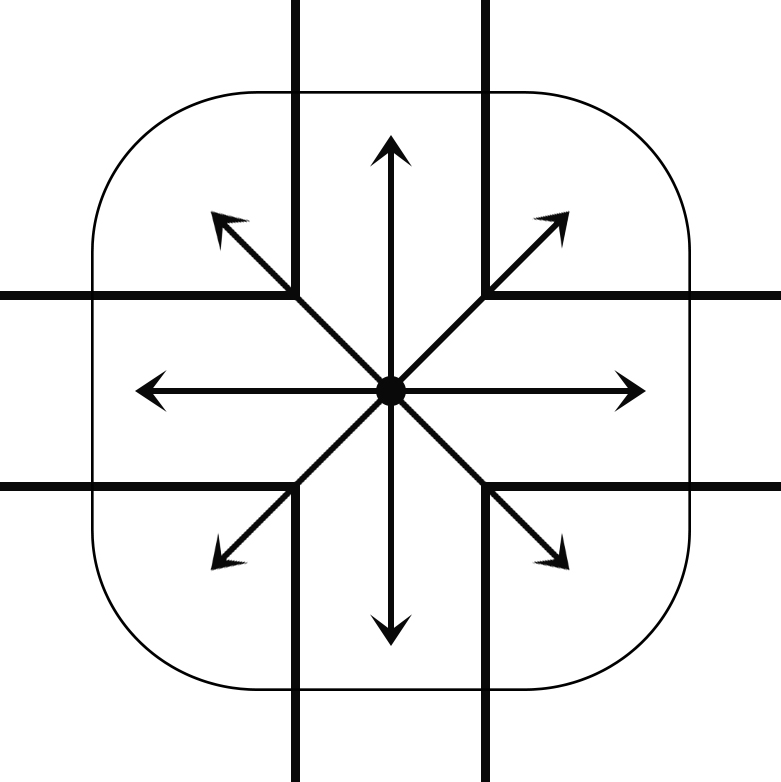
Type V (a circular symmetry of candlepower distribution)
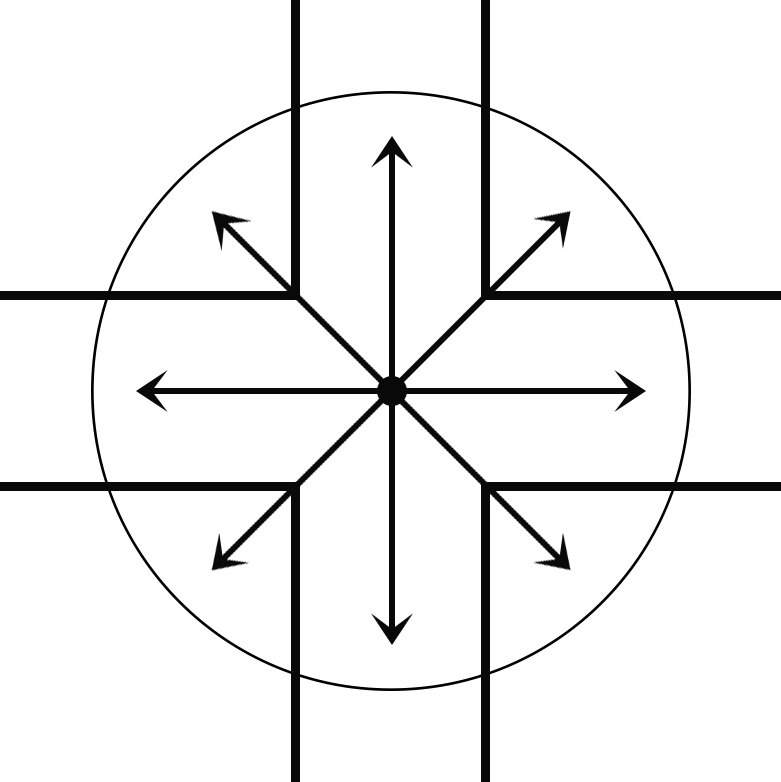
Type VS (a square symmetry of candlepower distribution)
Luminaire Classification System (LCS)
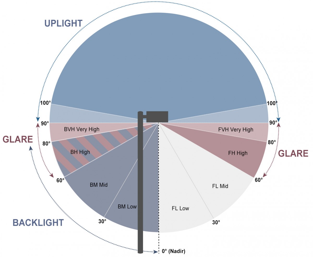
The effect of outdoor lighting systems on the environment are under increasing scrutiny. The presence of bright sources in the periphery of the field of view may compromise road visibility and cause feelings of discomfort. As such, precise cutoff of light is required in outdoor applications to eliminate urban sky glow (light pollution), light trespass, and glare. The IES BUG (Backlight-Uplight-Glare) rating system is designed to replace the deprecated "Cutoff" LCS (Luminaire Classification System). The new LCS establishes zonal lumen classifications for luminaires. Backlight, which is the light leaving the luminaire in the opposite direction to the main aiming angle of the light, is evaluated for high (60 - 80 degrees), medium (30 - 60 degrees) and low (0 - 30 degrees). Uplight considers the total light propagating from the luminaire in a near horizontal or above-horizontal direction. It's evaluated for high (skyglow: 100 - 180 degrees) and low (90 - 100 degrees). Glare is evaluated for forward light and backlight very high (80 - 90 degrees), forward light medium (60 - 80 degrees), and backlight medium (60 - 80 degrees).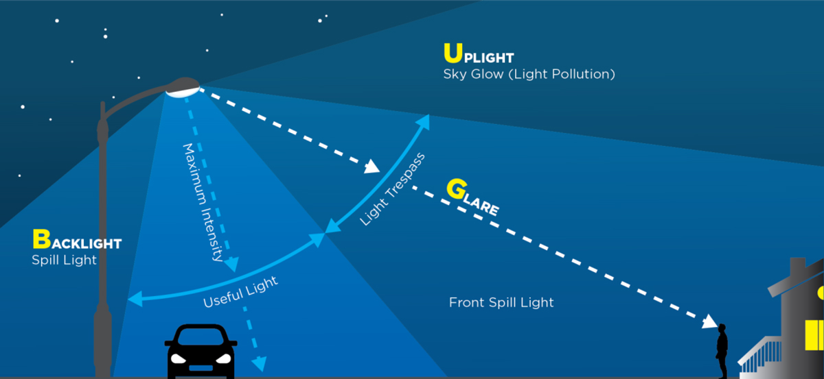
Glare control
Forward light defines lumen distribution in front of the luminaire (0° - 90° vertical, 90° - 270° horizontal). This primary solid angle is further refined into 4 vertical secondary solid angles:
- Forward light low (FL, 0° - 30° vertical)
- Forward light mid (FM, 30° - 60° vertical)
- Forward light high (FH, 60° - 80° vertical)
- Forward light very high (FVH, 80° - 90° vertical)
Back light describes lumen distribution in back of the luminaire (0° - 90° vertical, 90° - 270° horizontal). This primary solid angle is also divided into 4 vertical secondary solid angles:
- Back light low (BL, 0° - 30° vertical)
- Back light mid (BM, 30° - 60° vertical)
- Back light high (BH, 60° - 80° vertical)
- Back light very high (BVH, 80° - 90° vertical)
Uplight describes lumen distribution between 90° and 180° vertical, and 0° - 360° horizontal. Its secondary solid angles include:
- Uplight low (UL): Lumens between 90° and 100° vertical, 360° around the luminaire
- Uplight high (UH): Lumens between 100° and 180° vertical, 360° around the luminaire
IES BUG (Backlight-Uplight-Glare) rating system
Ingress Protection
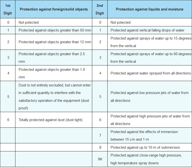
The electrical and LED compartments of LED street lights are required to maintain a high ingress protection (IP) rating to seal out moisture and dust that can reduce system performance over time. In general, the electrical compartment should be at least IP65 rated and the LED compartment or optical assembly should be at least IP66 rated. Optical assemblies with a low IP rating will cause moisture and corrosive gases to diffuse into the LED packages. This can substantially decrease the conversion efficiency of phosphor composites, lead to the formation of cracks in encapsulants, and result in degradation and discoloration of encapsulant materials.The sealing performance of gaskets will degrade when they're repeatedly stressed by pressure differentials within the enclosure. As seal performance declines, the integrity of the enclosure degrades accordingly. Therefore it is necessary to maintain constant pressure inside the luminaire enclosure. Street lights utilize the breathing membrane solution to equalize pressures within the enclosure. A pressure-stabilizing breather or membrane vent enables water vapor molecules to diffuse through the microporous membrane, thereby minimizing condensation and effectively preventing the internal vacuums or pressure buildups. At the same time, it serves as a durable barrier against liquid, dust, dirt and other contaminants.
The IP rating system
NEMA-to-IP Conversion
